Not rendering correctly? View this email as a web page here.

Hi there,

"Optimization" is a term that gets thrown around quite a bit. In this newsletter we’ll do a quick overview of Topology Optimization and Generative Design, and show examples of it currently in use today.

So, what’s the Difference?

There is no industry-wide agreement to the definition of these terms, but both of these technologies can be considered “Algorithm-Based Computer Aided Design" tools. In other words, you (the designer) will input some starting geometry, design constraints, and a goal, and the CAD/CAE software will automatically create some final geometry that meets your needs. Compared to the traditional "trial-and-error" method of design, using algorithms can result in very efficient designs with very organic-looking aesthetics. 

Different CAD companies have developed different algorithms for use in their CAD/CAE software (some more proprietary than others), so the terms get interchanged and misused a lot. Additionally, marketing tends to override the engineering often, so here we'll break it down to very simple terms. The two main types of algorithm-based design software are called Topology Optimization and Generative Design. The graphic below shows a direct comparison of the same design resulting from Topology Optimization (left) and Generative Design (right) using Autodesk’s Fusion 360 software:

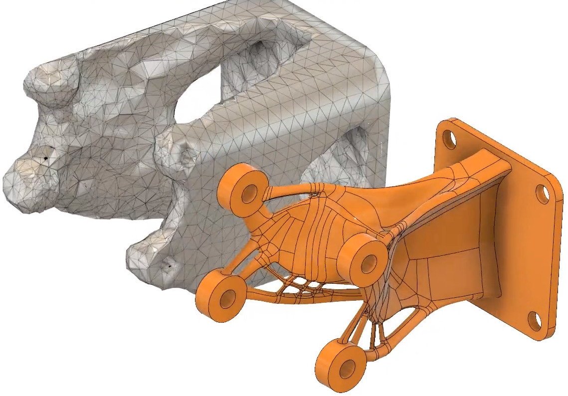
As you can see, the Top Opt part on the left requires quite a bit of post-processing before it can be manufactured versus the Generatively Designed one on the right.  

Topology Optimization software focuses on the removal of material from some baseline volume. Most often, this is done through the direct use of an underlying Finite Element (or Computational Fluid Dynamics) Analysis. Examples of types of design goals would reducing mass, or reducing aerodynamic drag forces while maintaining sufficient stiffness. The resulting geometry in these cases is a single, “optimized” structure. The final geometry appears as a mesh, and then must be post-processed into a usable BREP Geometry.

Generative Design software focuses on adding material between various baseline geometry, such as mounting hole bosses or flanges, resulting in a final shape. There may or may not be an underlying FEA (some of the code is quite proprietary), and there may or may not be a single answer. More often than not, Generative Design results in a number of different designs options which the we must ultimately choose one from.

In both cases, traditional FEA or CFD must be conducted on the final design to ultimately pre-validate the design prior to testing. However, an "optimized" design is more likely to pass the test, or exceed the performance goals as long as the criteria and goals have been setup properly. In many cases, the software can also handle a wide variety of manufacturing processes constraints, such as enforcing the design to be symmetrical or made of sheet metal, molding, casting, additive manufacturing processes.

Below is a comprehensive list of commercially available Top Opt and Generative software (if we missed one, let us know!)

altair1
ansys1
autodesk1
dassult1
frustrum2
paramatters1
siemens1
solidworks1


Furniture Design
In addition to the first commercial chair made from Generative Design on the left, and the Architectural Biomimicry design below, the following links are more really cool examples of Industry-specific applications of Topology Optimization and Generative Design software: 

Aero AEC Auto
Furniture Jewelry Medical


How Biomimicry Can Inspire Innovative Designs


Creo Simulate Structural Optimization Comparison Fastway Engineering

In the picture above, we compared the new Topology Optimization capabilities within PTC Creo against other design methods in an attempt to reduce the weight of a CubeSat which gets launched into space with a SpaceX Falcon 9 rocket. Check out this prime example of structural lightweighting in the latest addition to our Blog here!

LinkedInLinkedin Update:

Managing director, James Shaw, showed best practices in using FEA on an optical bracket for a nanosatellite. This project is straight from our newest class on structural optimization using PTC Creo and ANSYS. Connect with Fastway for the latest in unbiased CAD/CAE Industry and Professional Development news.

Connect on LinkedIn