Hi there,
We're going to be very blunt here, simulating Electronics is challenging. In this newsletter, we look at the three main reasons why and point to a few resources that can help.

Electronics are Multi-Scale
The first, and probably most challenging part of electronics is that it is multi-scale. As you can see above, electronics can range from microscopic transistor gates to massive data centers. Before you jump into any CAD/CAE software, the first thing to establish is at what scale to focus on. At Fastway, we call this the Level of Detail (LOD), and it is something we define before we begin preparing the geometry and mesh (i.e. "Pre-processing"). Below are three ways to model and analyze a microchip for heat transfer, depending on the LOD required.

On the left, we see full detail at the "component level", in the middle we see it as a simple rectangle at the "board level" and on the right it is not even included at the "system level".
To address this, CAE companies have developed software for different scales. For example, Ansys Icepak has a huge library of detailed 3D components and Autodesk CFD has a built in "Compact Thermal Model" which can provide additional details of a component without having to mesh it.
Electronics are Multi-Disciplinary
An Electronic product requires a multidisciplinary approach to design, especially across the Electrical and Mechanical Hardware teams. In the CAE world, we call this the ECAD-MCAD connection, where design data can be easily (and parametrically) transferred between sources. Both SOLIDWORKS' direct connection and PTC Creo's Collaboration Extension (shown below) allow for quick design iterations while doing simulation-in-the-loop alongside ECAD tools like Altium, Cadence and Mentor.

With ECAD mainly taking place in 2-D, and MCAD manly taking place in 3D, extensive libraries connect the two to allow full detail in both environments.
Electronics are Multi-Physical
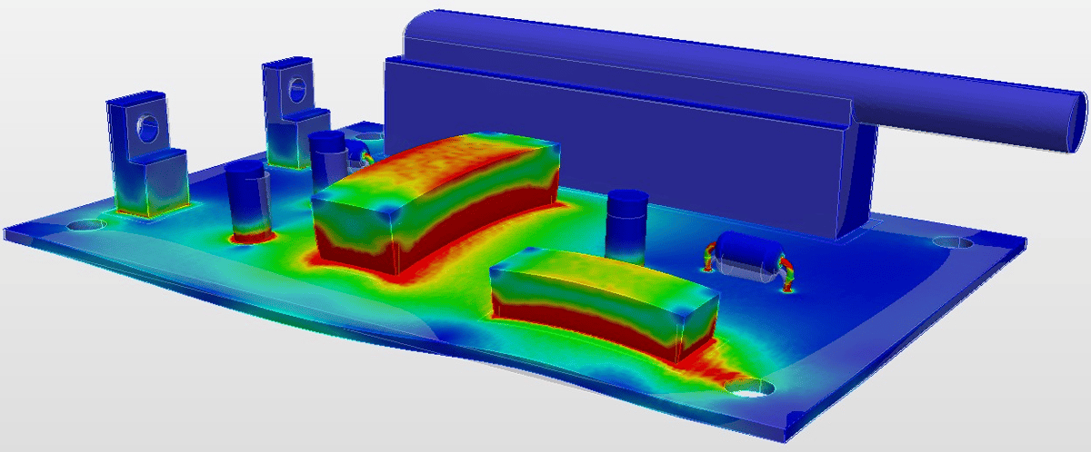
The Engineering behind an Electronic System bridges almost all physics, from Chemical and Electrical, to Thermal, Fluid and Structural. Probably the most common use of a multi-physics analysis that is used for Electronics is a Thermal Stress Analysis. In this analysis, the temperature profile results from a thermal analysis are used as a load for a static structural analysis to exploit the Coefficient of Thermal Expansion. Our 5-Day Intro to FEA classes cover Thermal Stress on Day 4.

Here's an example of using Onshape CAD and Simscale FEA to perform a thermal stress analysis on a Printed Circuit Board completely in the cloud.
Make sure you use the right tool for your next Electronics Cooling Simulation. FEA has limitations of analyzing Conduction only (as only solids are meshed), so whenever Convection and Radiation play a significant role, you must use a CFD tool no matter what the scale is.